


The suitability of valves for operation in high pressure drop conditions depends on the design of the valve’s internal components.
The parameter determining the permissible critical pressure drops under throttled or cavitation flow conditions is the pressure recovery factor FL.
∆p = K∙FL2(p1-pv)
where:
K=0.85 – for throttled flow
K=0.67 – for cavitation
The value of the pressure recovery factor FL may vary between 0.5…1.0 depending on the type of valve. High pressure recovery valves (butterfly valves, ball valves) have a low FL value and are not suitable for operation under throttled flow and cavitation conditions.
For these applications, the design of the valve should ensure that the maximum FL values are achieved.
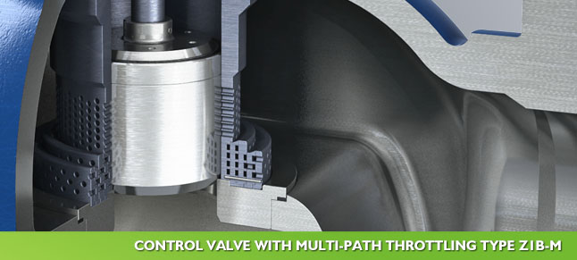
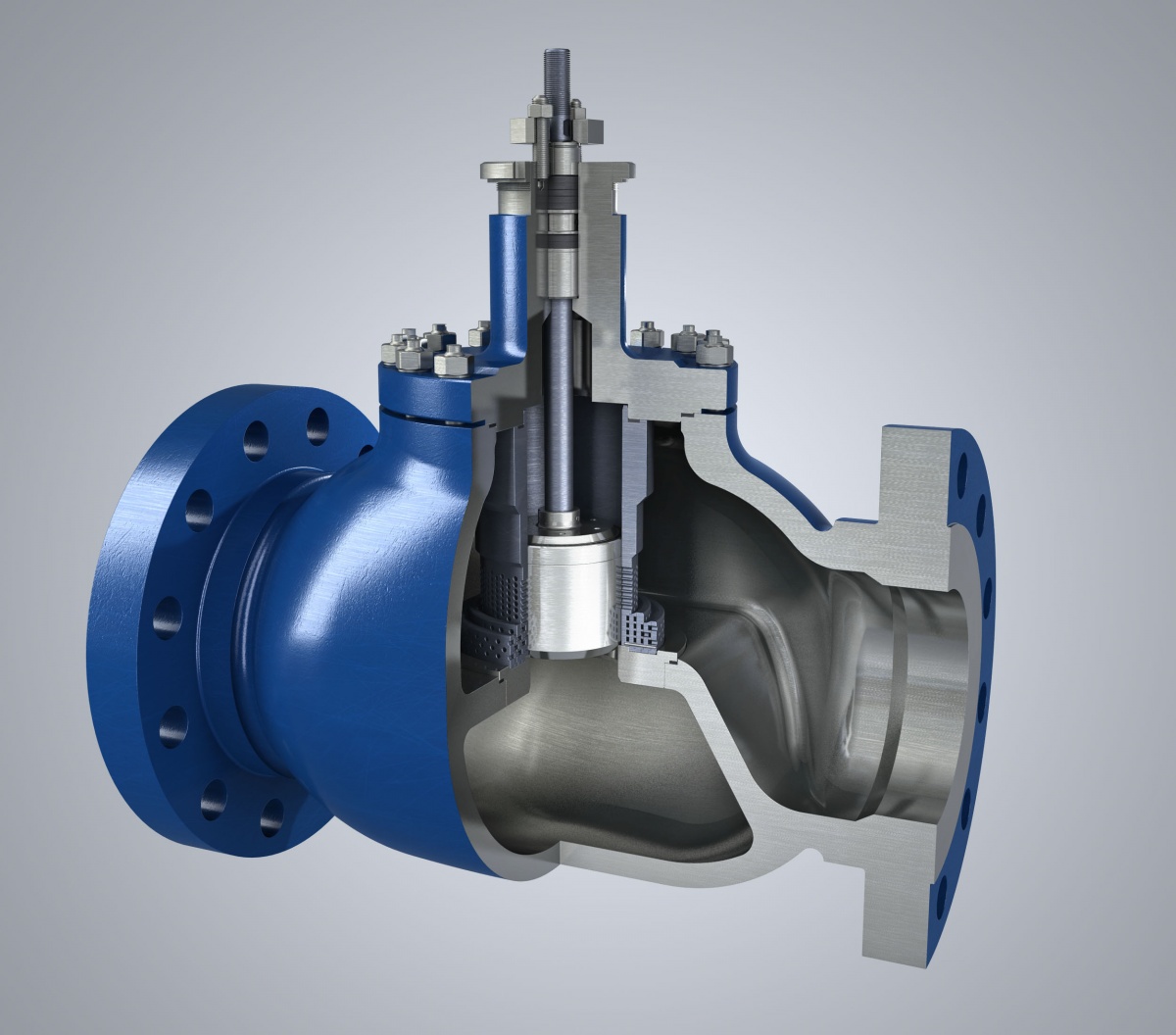
These requirements are met by Z1B-M valves with labyrinth multipath flow direction of the stream in the valve throttling elements (FL=fi0.975).
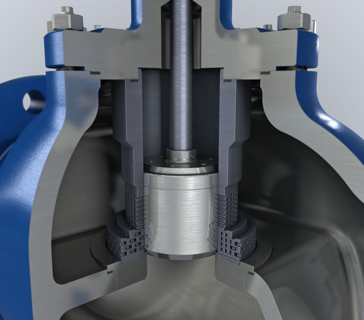
In the set of throttling cages there are channels ensuring separation and refraction of the stream while maintaining a gradual increase of the flow field.
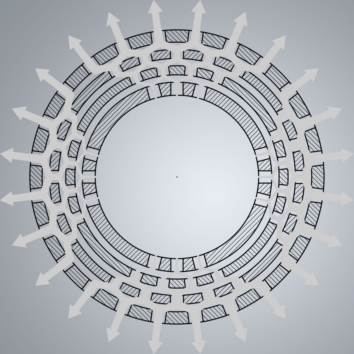
The number of throttling cages depends on the pressure drop.
The illustrations above show valve Z1B-M, DN200, PN100, Kv200L, for water parameters p1=80 bar, p2=5…80 bar, qv=175 m3/h.
At the beginning of the opening, four throttling structures are used at maximum pressure drop, two at ∆p drop, and at maximum throughput the flow is carried out at minimum throttling.
The valve is used to control high-pressure wash water in the suspension installation in the Bełchatów Power Plant and meets the requirements of the process without reservations.
Z1B-M valves are designed for liquid and gaseous media and a number of applications in the power engineering and gas industry confirm the high evaluation of their suitability for the most difficult working conditions.
We invite you to cooperation.